BreadboardBot
Parts and tools
To build the BreadboardBot you will need to obtain the following parts and tools.
Body
| Image | Component | Price | Notes |
|---|---|---|---|
 |
Xiao RP2040 | $6 | The Seeedstudio Xiao series includes several microcontrollers with the same, pin-compatible form-factor. Moreover, there are pin-compatible boards from other vendors (example). Most of those could be used as a drop-in replacement to the Xiao RP2040 in the BreadboardBot (with appropriate update to the code and, maybe, some wiring changes). This is one of the things that makes the BreadboardBot exciting (e.g. Xiao ESP32S3 Sense is a pin-compatible microcontroller with Wifi, Bluetooth, microphone and camera). Pin compatibility with the Xiao is not a strict requirement either. For example you can build a line-follower BreadboardBot or a Bluetooth-joystick-steerable Breadboardbot with the M5Stack Atom. The Xiao RP2040, however, is the current “recommended starter model” for making a BreadboardBot. It is cheap (do get a few replacements to break), beginner-friendly (due to CircuitPython support) and quite tolerant to some of the sloppy electrical connections used in the bot. In any case do not get the Xiao SAMD21 (which may be tempting as it is sold with presoldered headers). This model seems to operate the motors incorrectly when powered by the 4.5V battery of the BreadboardBot. It also has way uncomfortably little space for storing your scripts. As I try BreadboardBot with other MCUs more examples will appear here. |
 |
Mini-breadboard | $0.5 | |
 |
2 x FS90R continuous servo + wheel | $6 | The version with lego-style wheels is the most convenient (as you can easily take them off and put back on). Note that the linked servos are not the most reliable and you might want to get a backup or two. |
 |
or 2 x Geekservo continuous servo + wheel | $12 | Alternatively, you can get these “GeekServo” motors with LEGO-style axes. They cost more, but are more colorful and seem slightly more precise and reliable. Note that they are slower than the FS90R servos above. |
 |
3 or 4xAAA battery box | $1 | Make sure you get the battery box with an on-off switch. Most examples work best with 3xAAA batteries, however for some the 4xAAA battery box is better (especially if you are using rechargheable NiMH batteries), so it may be a good idea to get one of each. |
 |
Self-adhesive caster ball | $0.4 | The caster ball is nice, but optional. |
NB: AliExpress links here point to somewhat arbitrarily chosen sellers that I personally used to order the parts. They might become stale or you might be able to find the same components cheaper (for the particular quantity you need) elsewhere. The prices match what I paid when ordering components for 5 kits, including shipping.
Sensors / actuators
You can plug a variety of breadboard-friendly gadgets into the robot, as long as they don’t have too many pins and work with 3.3V power.
The components listed below are just a small selection of things that have been tested so far and are supported by some of the provided code examples.
| Image | Component | Price | Notes | Example |
|---|---|---|---|---|
 |
2 x Line-tracker sensor | $1 | Make sure you get the model with pins ordered OUT, VCC, GND (when the sensor is looking down). | [1] |
 |
RCWL-1601 sonar | $1.5 | NB: This is not the popular HC-SR04 (“blue”) sensor. The blue one requires 5V input, this one works with 3.3V. | [1] |
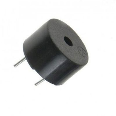 |
Passive buzzer | $0.2 | There are many options, I’ve yet to find one that fits the breadboard perfectly. | [1] |
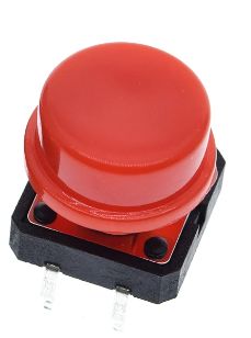 |
Button (1, 2) | $0.05 | There are many options, I’ve yet to find one that I like best. | [1] |
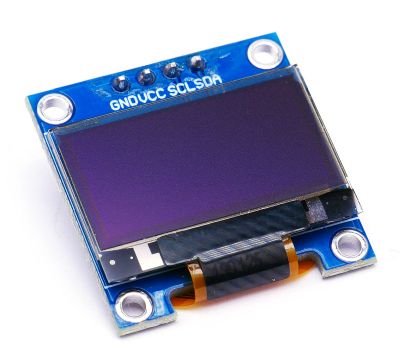 |
0.96” SSD1306 OLED | $2 | [1] | |
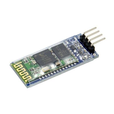 |
HC06 Bluetooth serial transceiver (4-pin) | $2.4 | [1,2] | |
 |
MPU-6050 | $1.2 | [1,2] | |
 |
DHT11 humidity & temperature sensor | $0.7 | [1] | |
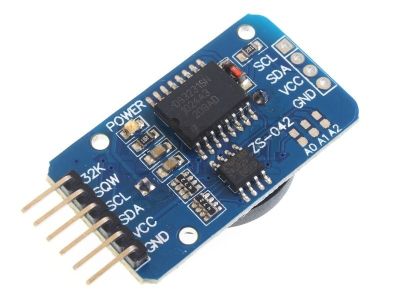 |
DS3231 real-time clock | $1.6 | [1] | |
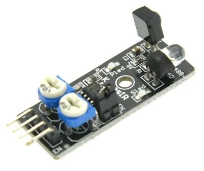 |
IR proximity sensor | $1 | [1] | |
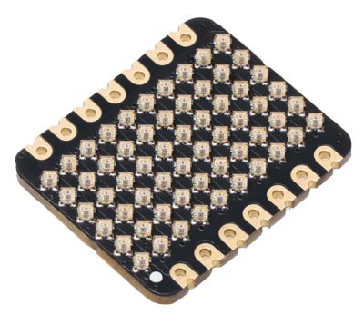 |
Xiao 6x10 RGB Matrix | $5 | Get two of them if you have the budget. You will also need 17mm pin headers to attach the matrix suspended above the main microcontroller. | [1] |
Expendables
You will need some expendable materials to assemble the robot as well as a set of breadboard wires.
| Image | Component | Notes |
|---|---|---|
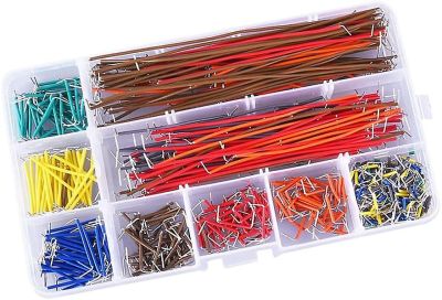 |
Breadboard jumper wire set | Alternatively, you can also make neat breadboard jumpers yourself from 22 AWG solid-core wire as shown here. Note that those are not “DuPont” jumper wires. 4 female-to-female and 4 male-to-female DuPont jumpers are used in the two self-balancing examples, however, so you might want to have a few of these around as well eventually. |
 |
2 x M2 bolts 5-8mm | The bolts are optional - you can just stick the motors on the back of the breadboard without them. However, adding the screws makes the construction much more durable. The required length of the bolts depends on whether the head will sink inside the opening. |
| Hot glue | In theory this can be any glue that will stick servo connectors to the side of the breadboard. I was hoping superglue would work, but it somewhy did not hold at all for me. Hot glue did the job very well. This may depend on the actual plastic used for the breadboard - it seems there are slight variations. | |
| Two-sided sticky tape | Any two-sided tape should do, but I really like the linked one (the either the 20mm or the 30mm-wide one will do). Worth having at home in general. | |
 |
Pin headers | Firstly, you will definitely need the “usual”, male, 11mm headers (2 sets of 7 pins) to solder onto the MCU. In addition, headers for the battery box are needed and there are two options. The “basic” one is to solder two 11mm male pin headers to the battery wires (in this case you might also want to get some heatshrink or insulation wire). A fancier option (less prone to a battery misconnection that can burn your MCU) is to crimp a 3x1 female header on the battery wire (you will need a crimper tool for that) and have it plug onto male headers sticking out of the breadboard. For that you will need to get three 15mm male pin headers. For the RGB matrix examples you will need a row of 17mm male pin headers as well. Four 21mm male pin headers are used in the self-balancing example. |
Tools
You will need scissors to cut the sticky tape, a screwdriver for screwing the bolts, a hot glue gun (unless you find a different glue for fixing servo connectors on the breadboard) and a soldering iron to solder pinheaders to the MCU. The two additional (optional and perhaps less common) tools that I personally ended up using are:
| Image | Component | Notes |
|---|---|---|
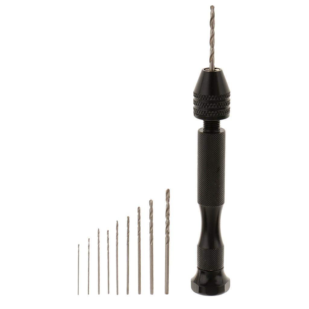 |
Hand twist drill | A small hand-twist drill (which you can get for $3 sometimes) can be quite useful for making the 2mm holes in the servos which you need to then bolt them to the breadboard. You might find different ways of getting those holes or, as mentioned above, simply avoid bolting the motors to the breadboard completely. |
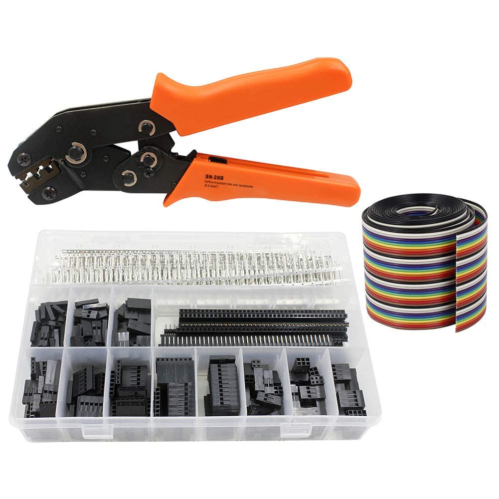 |
Dupont wire crimper tool | This is optional and only needed if you want to make a “fancier” battery connector. |
Extras
The absolutely optional but incredibly convenient extra is:
| Image | Component | Notes |
|---|---|---|
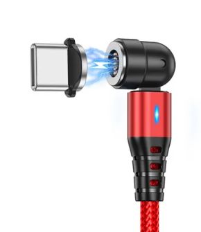 |
Magnetic, 90-degree twistable USB cable | Allows you to easily connect to the microcontroller on the breadboard without having to remove the wheels every time. |
Once you’ve gotten all the parts, proceed to assemble them.